Mechanical Die Lifters/Rollers

Mechanical/Portable Die Lifters/Rollers

When to Use:

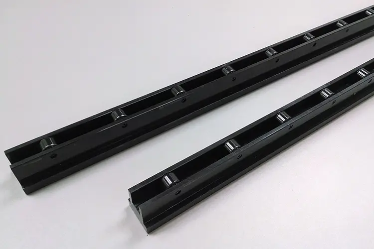
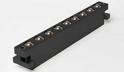
Stationary Spring Loaded Die Lifter Rails.  Providing multi-directional movement, these rails (roller bars) are used for medium to lightweight dies when die density is low. They are also used when the need for mechanical only or unique layouts drive the decision process. Springs automatically lift die when clamping is removed from the die.

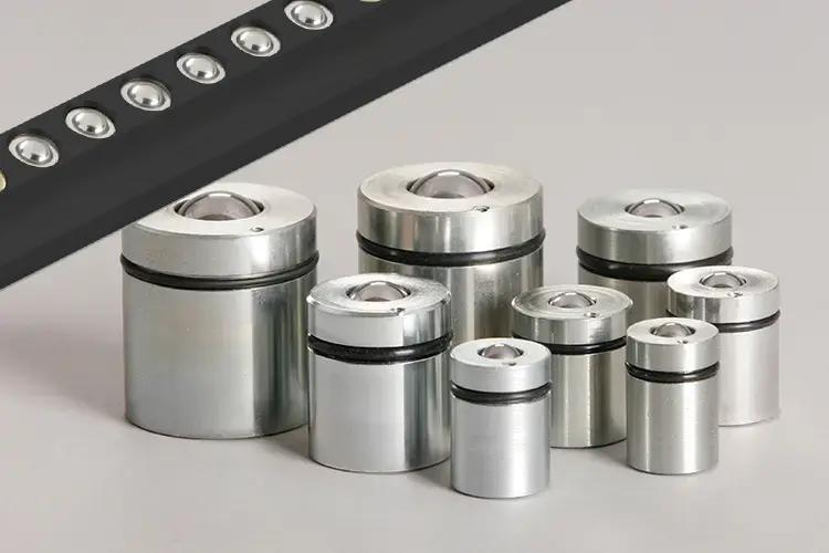
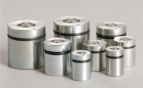
Stationary Spring Loaded Ball Cartridges.  Installing an array of single ball cartridges also provides multi-directional die movement without operator involvement. Cartridges can be placed anywhere in the bolster to avoid taking up slots needed for clamps. Cartridges work great in Non-Slotted Bolster applications.

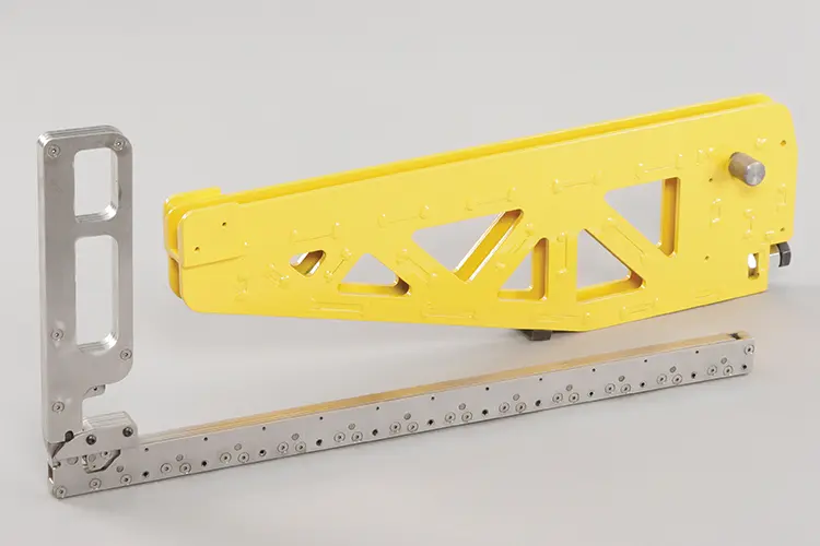
Portable Die Lifters.  Hand operated lifters (roller bars) work well with common slots among presses, providing maximum ROI by allowing a single set of lifters to serve die changes on an entire group of presses.

Fixed Height Roller Bars / Pre-Rollers. Providing conveying movement only, these roller ball rails fit tight locations for easy movement of lifted dies to other locations.

How they work:

Spring loaded ball cartridges and spring loaded die lifter rails are permanently installed in the bolster. During clamping, the clamp force compresses the springs and forces the balls below the surface. When clamps are released, the spring forces lift the balls and the die with them. The die is now ready for removal/repositioning.

Portable die lifters provide a large mechanical advantage by multiplying hand/handle motion to lift the die. The large lever action easily lifts the die for either (1) die lifting only – insert in slot and lift the die allowing the die to be rolled onto a cart, etc. or (2) die lifting and movement onto a bolster extension, allowing die pickup with forks.

Stationary Die Lifter Rails and Stationary Spring Loaded Ball Cartridges
Portable Die Lifters
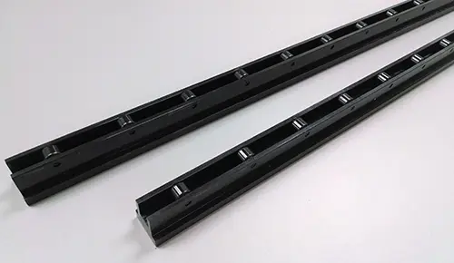
Static Fixed Height Roller Bars

Mechanical (Stationary) Spring Loaded Die Lifter Rails

How to Determine Available Die Lifter Rail Options

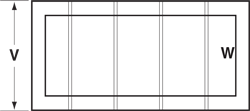
1. List out die sizes and weights.  Calculate die load per foot, per pair of lift rails.  (W=width in feet)
Die 1 Weight ________ ÷ W = ________ lbs./ft./pair
Die 2 Weight ________ ÷ W = ________ lbs./ft./pair
Die 3 Weight ________ ÷ W = ________ lbs./ft./pair

Determine heaviest die per foot. Heaviest die density lb./ft./pair = __________________

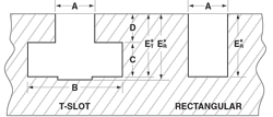
2. Measure T-Slot or Rectangular channel throat.
If A = .800 to 1.000, use Narrow Rails
If A = 1.000 to 1.25, use Wide Rails
If A = <.800 or >1.25, contact PFA

3. For the heaviest die, check the number of available slots under the die:  Number of available slots = _______________

4. Take the die density from Part 1 and find the closest larger lbs./ft./pair in the chart to the right.  Then move across the chart to find the minimum number of slots, keeping in mind the Narrow or Wide from Part 2 and the number of available slots from Part 3.  If your application does not support the number of slots needed, see page 11 (Hydraulic Die Lifters/Rollers) or call PFA for assistance.

5. Record the rail model number and number of needed rail slots from the chart: Model ___________________    No. of Slots _________

6. For the selected model, confirm that the number of rails always supports the dies as follows:  [W ft] x [Chart lbs./ft./pair] x [No. of Rails] / 2 = [Lift Capacity] > [Weight lbs.]

Die 1 ______ x ______ x ______ ÷ 2 = ______  >  ______
Die 2 ______ x ______ x ______ ÷ 2 = ______  >  ______

Ensure lift capacity is greater than die weight.

8. Use the Model Number and Bolster Length (V) to determine the slot length to fill.  Lifters should start at the loading side of the bolster and end near the other side for maximum versatility.

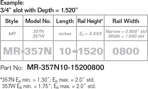
9. Use slot dimensions to determine rail part numbers.  Use of multiple 7”, 10” or 12” rail sections versus one long rail is recommended to take advantage of stock parts and flexible installations.

Quick Die Change QDC Spring Loaded Die Lifter Rail

Temperature Rating: Dry to 400˚ F (Intermitent to 550˚ F). For moisture applications or use above 400˚ F stainless steel rollers are recommended.

Quick Die Change QDC Spring Loaded Die Lifter Rail
Bolster Dimensions QDC Quick Die Change
Slot Dimensions QDC Quick Die Change
Die Density
(lbs./ft./pair)
Narrow Slot Wide Slot
357N
(1,800 lbs./ft./pr.)
357W
(2,000 lbs./ft./pr.)
1,800 2 Rail Slots 2 Rail Slots
2,000 3 Rail Slots 2 Rail Slots
2,700 3 Rail Slots 3 Rail Slots
3,000 4 Rail Slots 3 Rail Slots
3,600 4 Rail Slots 4 Rail Slots
4,000 5 Rail Slots 4 Rail Slots


Length
(in)
357N Max
Load Capacity
(each section)
357W Max
Load Capacity
(each section)
Ball Rollers
(each section)
7 600 lbs. 690 lbs. 6
10 800 lbs. 920 lbs. 8
12 900 lbs. 1035 lbs. 9

Other sizes available. Please contact PFA for details.

Static Fixed Height Roller Bars

How to Determine Available Static Rail Options

1. List out die sizes and weights.  Calculate die load per foot, per pair.  (W=width in feet)
Die 1 Weight ________ ÷ W = ________ lbs./ft./pair
Die 2 Weight ________ ÷ W = ________ lbs./ft./pair
Die 3 Weight ________ ÷ W = ________ lbs./ft./pair

Determine the heaviest die per foot. Heaviest die density lb./ft./pair = __________________

2. For the heaviest dies or those with the greatest die density, check the number of required lines under the die:
Take the die density from Part 1 and find next largest lbs./ft./pair in the chart to the right Then move across the top to find the needed number rail lines.

3. Record the rail model number and number of needed rail lines from the chart:
Model MR-947 or MR-947HD No. of Lines _________

4. Given the total length needed to move the die, calculate the number of 12 in and 18 in sections needed for each line and multiply by the number of lines to get total number of each.

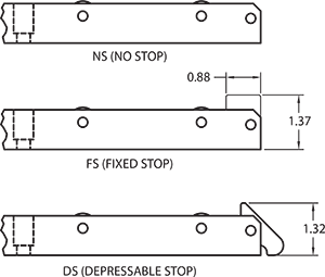
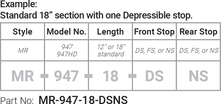
5. Determine if any section needs a Fixed Stop (FS) or a Depressible Stop (DS) to prevent movement beyond the end of the section. All sections not at the end of a line (in the middle) should have No Stop (NS) on each end.

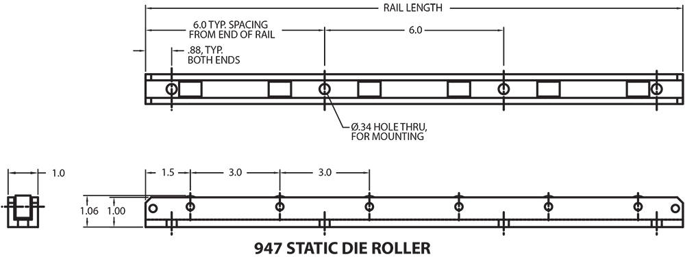
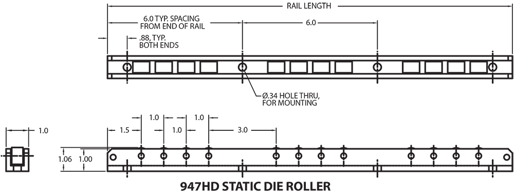
Static Die Roller Diagram
Front sections are often MR-947-DSNS for Depressible Stop on one end and No Stop on the other. Rear sections are often MR-947-FSNS for Fixed Stop and No Stop.

6. Use slot dimensions to determine rail part numbers. The use of multiple 12” or 18” rail sections versus one long rail is recommended to take advantage of stock parts and flexible installations.

Static Fixed Height Roller Balls How to Order
948 Inline Rollers
Bolster Dimensions QDC Quick Die Change
947 Static Die Roller diagram
947HD Static Die Roller diagram
Die Density
(lbs./ft./pair)
Standard Heavy Duty
MR-947
(4,000 lbs./ft./pr.)
MR-947HD
(8,000 lbs./ft./pr.)
4,000 2 Rail Lines 2 Rails
6,000 3 Rail Lines 2 Rails
8,000 4 Rail Lines 2 Rails
10,000 5 Rail Lines 3 Rails
12,000 6 Rail Lines 3 Rails
16,000 7 Rail Lines 4 Rails


Length
(in)
357N Max
Load Capacity
(each section)
357W Max
Load Capacity
(each section)
Ball Rollers
(each section)
12 4,000 lbs. 8,000 lbs. 4 or 8
18 6,000 lbs. 12,000 lbs. 6 or 12

Other sizes available. Please contact PFA for details.

Stationary Spring Loaded Ball Cartridges

Quick Die Change QDC Spring Loaded Die Lifter

Standard Sizes (Typically in Stock)

*Many non-standard sizes available. Call PFA for non-standard and custom sizes.

Part No.* Allowable Load
lbs. per Cartridge
Ball Diameter a b Hole A
+.005   -000
Hole B
+.005   -000
Hole C
+.005   -000
MR-305-12 45 lbs. ¾ 1⅛ .750” 1.130” 1.110”
MR-305-13 45 lbs. 13/16 1⅛ .813” 1.130” 1.110”
MR-305-15 70 lbs. 15/32 15/16 1⅛ .937” 1.130” 1.110”
MR-305-16 70 lbs. 15/32 1 1⅛ 1.000” 1.130” 1.110”
MR-305-19 115 lbs. 1-3/16 1⅜ 1.187” 1.375” 1.355”
MR-305-21 115 lbs. 1-5/16 1⅜ 1.312” 1.375” 1.355”
MR-305-25 150 lbs. 1-9/16 1.562” 1.770” 1.750”
MR-305-26 200 lbs. 1⅝ 1.625” 1.770” 1.750”

1 – Use hole information for mode exact dimensions and proper bolster modifications.

2 – Please note difference in hole depth.  Drill point allows cartridge to sit deeper due to chamfer on bottom of cartridge housing.

Damaged cartridges can readily be extracted and replaced.  Thread a 4-40 UNC screw into the thread hole and pull cartridge out.

Model 305 allows movement of dies in any direction.  A push of about 2-4% of die weight is usually required to move a die.

Install a pattern of Model 305 on a press bolster.  Keep die weight and footprint in mind to ensure that a die can be adequately supported.  When a die is clamped, the die lifter cartridges under the die will compress.

Quick Die Change QDC Spring Loaded Die Lifter

Hand Operated and Portable, Mechanical Die Lifters and Lifter Systems

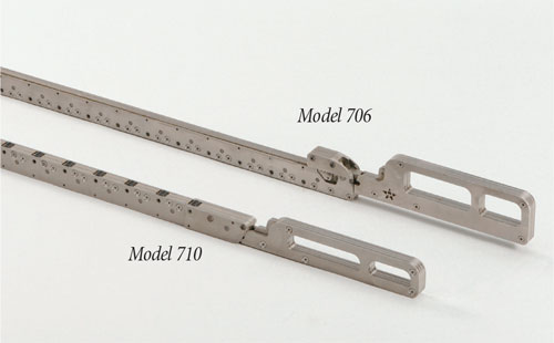
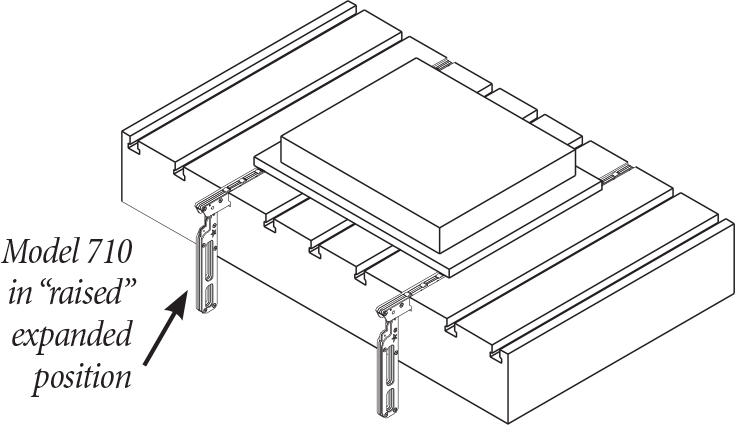
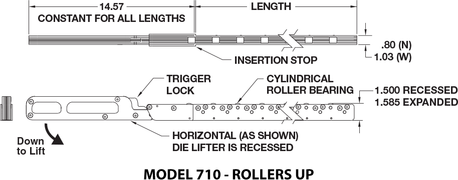
Model 710.  The popular and portable Mechanical Die Lifter Rail is typically installed in a slot in the bolster with rollers up.  The lifters are mechanically actuated by hand to the lifted position prior to die insertion and then released to lower the die.  (Note: The amount of force required to elevate the die varies with handle position and is in the range of 1.5% to 2.5% of die weight.  2,000 lb. die = 30-50 lbs.) To allow portable lifters to be taken from press to press, slots are shimmed to a common slot depth among presses.  Model 710 lifters are used with standard Bolster Extensions.

The lifter is inserted, handle up, under the die.  When the handle is moved to the horizontal position the die lifter expands .085” to lift the die approximately .060” above the bolster surface.  Available in .80” Narrow (N) 3/4” slot and 1.03” Wide (W) 1” slot versions, these portable units can be used in multiple presses, greatly reducing QDC equipment costs.

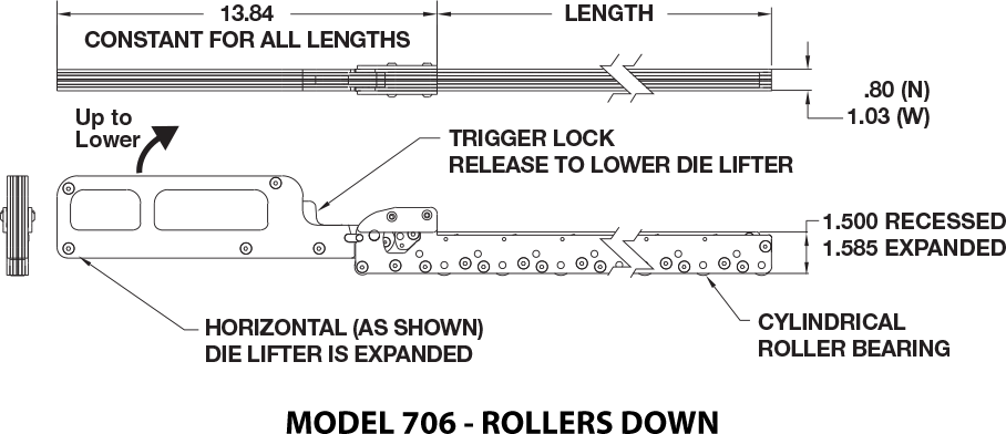
Model 706.  A mechanically actuated die lifter which is used, rollers down, to move dies from “slotted” Bolster Extensions or a die transfer table onto the bolster and vice-versa. With rollers down, this acts to add wheels to the die.  (See the combined Model 706 lifter and Bolster Extension options).

Model No. Standard Lengths Max  Load Capacity per pair
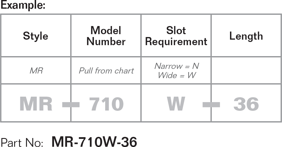
710N (3/4” slot) 24”/30”/36”/42”/48” 8,000 lbs.
710W (1” slot)
706N (3/4” slot) 24”/30”/36”/42”/48” 8,000 lbs.
706W (1” slot)
Quick Die Change QDC  Mechanical Die Lifter Portable
Quick Die Change QDC  Mechanical Die Lifter Portable model 710 rollers up
Quick Die Change QDC  Mechanical Die Lifter Portable model 706 rollers down

Mechanical Die Lifter Operational Demonstration Video

The popular and portable Mechanical Die Lifter Rail is typically installed in a slot in the bolster with rollers up. The lifters are mechanically actuated by hand to the lifted position prior to die insertion and then released to lower the die. (Note: The amount of force required to elevate the die varies with handle position and is in the range of 1.5% to 2.5% of die weight. 2,000 lb. die = 30-50 lbs.) To allow portable lifters to be taken from press to press, slots are shimmed to a common slot depth among presses. Model 710 lifters are used with standard Bolster Extensions.

In the video, both lefters are inserted, handle up, under the die. When the handle is moved to the horizontal position the die lifter expands .085” to lift the die approximately .060” above the bolster surface. Available in .80” Narrow (N) 3/4” slot and 1.03” Wide (W) 1” slot versions, these portable units can be used in multiple presses, greatly reducing QDC equipment

¿LO NECESITA REPARADO DE INMEDIATO? PFA OFRECE SERVICIO REAL™

Aunque la mayoría de los productos de PFA son diseñados a medida, los artículos más críticos se mantienen disponibles para una emergencia. ¿Lo necesitas en 4 horas o menos? ¡Podemos hacerlo! Con el soporte técnico en tiempo real, los productos disponibles y envío el mismo día, a menudo podemos hacer que todo vuelva a la normalidad antes de que hayas tomado el café matutino. Eso es SERVICIO REAL™ (REAL SERVICE™).

¿TIENE UN PROBLEMA DIFÍCIL DE RESOLVER? PFA ES LA SOLUCIÓN.

Trabajamos con nuestros clientes para resolver los problemas existentes y podemos diseñar soluciones personalizadas cuando sea necesario. Con más de 25 años de experiencia en la revisión de aplicaciones y el suministro de productos personalizados, es probable que PFA ya tenga diseñada la solución a tu problema. ¡Llámanos hoy y cuéntanos como podemos ayudarte!

¿SE HA PREGUNTADO CÓMO INCREMENTAR LA PRODUCCIÓN? PFA TE LIBERA DE RETRASOS Y DEMORAS.

Con una solución comprobada de "lean manufacturing" de PFA, tu aplicación siempre funciona. El uso de un sistema de acción lateral KOR-LOK® resultará en un tiempo de diseño y fabricación más corto y reducirá los tiempos de desarrollo. Los clamps de cambio rápido de troquel (QDC) están en stock y listos para enviar, por lo que puede comenzar a ahorrar tiempo y dinero con SMED hoy mismo. Desde piezas de repuesto hasta soluciones complejas, PFA es la respuesta para una producción más rápida y con mayor utilidad.