The injection molding process dates back to 1872, when the Hyatt brothers, who invented the first machine, patented their idea. And it has not rested since then. But as time moves on, more and more complex molds are needed. These complex molds come with complex geometries and undercuts. You must know how to choose the correct cylinder before you start molding. This article will inform you of simple calculations and other things to consider when setting up your machines.
What Force Will Be on the Core?
One thing you must consider is the force that will be put on the core. The designer and operator of the injection molding machine can use the maximum projected area and the intended injection pressure to calculate the core force.
The maximum projected area (C) is found by sectioning the core at its largest point to be exposed to plastic. This is measured in square inches. Maximum injection pressure (P) is the nozzle pressure in pounds per square inch (psi). Once those two measurements are obtained, then the core force (F) can be found by simply multiplying them together (F=CxP).
Options for Side-Action
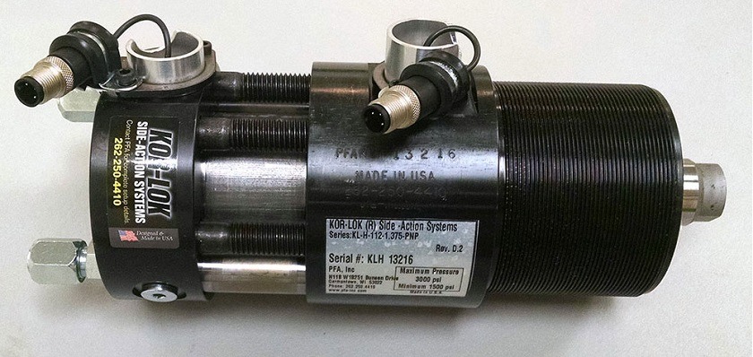
Side action is what gives your molds those undercuts, or the spaces in the mold that cannot be obtained by the straight pull method. There are a few possibilities for side-actions you can choose from – Cam pin with a heel, Cylinder with Heel, Cylinder only, or a Side-action system. The first two options use heel blacks to position the core; however, flex and compression are common issues with these options. The last two options help eliminate these issues. They will require you to calculate the core force and cylinder force.
Basics of Cylinders
Cylinders, which will be used in your injection process, have two main types of force. The push or extend force (M) and then pull or retract force (N). Both of these forces are important when choosing the correct cylinder for the job. To calculate both forces, you will need to know the Hydraulic supply pressure (H psi), Bore diameter of the cylinder (B inches), and Rod diameter of the cylinder (R inches). Once these specs are known, the push/extend force will be calculated as
M = H x [(π x B20/4]
and the pull/retract force will be calculated as
N = H x [(π x B2)/4 – (π x R2)/4].
Retract Force is critical when considering friction from material shrinkage.
Cylinder Sizing
There are two main sizes of cylinders for you to choose from. Standard cylinders are used if the machine’s cylinder hydraulic pressure is known and used during the injection. If so, then you will find the minimum bore size to be equal to √(4𝐹)/(𝐻𝜋). Nonstandard cylinders will be used if the pressure is not used. They will help maintain the high output force without using hydraulic pressure.
These simple calculations can assist you when choosing the correct cylinder for the job. Make sure you do the work before you run the machines to ensure that your molds come out flawless.
PFA manufactures locking cylinders, and core pull cylinders for molds and dies; quick mold change and quick die change systems for injection molding, die casting, and metal stamping; locking and braking actuators/cylinders for work cell and heavy industrial applications; and robotic end-effectors, grippers, and gripper pads for robotic applications. Both off-the-shelf and custom solutions are available to make your application a success. Contact a customer service representative for further inquiries.
Why Choose PFA, Inc.?
Understanding the effects of injection on the core, slide, and associated components is critical to selecting the best side-action method for a given application. There is only one KOR-LOK, and you can only get it at PFA. PFA’s team works to determine the best system for your application, design, and most importantly, your part or product. Let us help you get a grip on your automation system by contacting us today or calling 262-250-4410 for a free application review. Your success is important to us!


