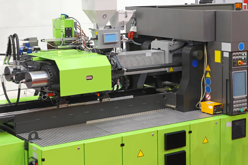
Any time a new injection mold is completed and ready for use, it is vital to ensure that the mold maker sets up in the injection molding machine to perform a test run. The process of setting up an injection molding machine is often much more than just loading and fixing the mold and pressing start. In fact, there are several key things to do after the injection mold has been clamped. This article will explore each step in the injection molding machine setup process to ensure the best-finished product possible.
Mold Height
Determining the proper mold height is arguably one of the most critical starting points when a new injection molding machine setup is required. During this process, the machine clamping force is calibrated to meet the particular mold dimensions. Each brand of injection molding machine will have its own method for setting mold heights – likely requiring a manual reference if an operator does not already know the process.
Mold height setting requires two phases to be correct. First, the initial setting should be done when the mold is clamped and the injection molding machine is closed. This will make the clamping of the mold on fixed machine plates possible. The second and final setting will be completed after the mold heater and cooling system are connected and the injection mold machine reaches the target temperature. This step is essential because the mold dimension will change due to increased or decreased temperatures.
Mold Heater/Cooling
Mold heater/cooling connections bring the injection mold to the needed process temperature. During this phase, energy will be added or removed from the mold. To ensure the process temperature is achieved, water or oil will be directed through the mold with at least one in and one out connection – referred to as a set.
Any unique schematics required for the mold heater/cooling connections can be found in the molding datasheet. If no special connections are present, connecting as many sets as possible will increase temperature control performance. Once mold heater/cooling connections are in place, functionality can be tested by feeling if the contacts have a noticeable temperature shift.
Hot Runner Connections
Some injection molding machine brands will be designed with a «hot runner system.» In these instances, there will be a designated runner that ejects from the injection mold during the final ejection of the plastic part. Often, this runner will be melted to the mold and injected into the cavity during the next cycle.
An electric heating system will be built into the injection mold that an internal or external control system can control to ensure the plastic remains at the correct process temperature. Before connecting a hot runner system, ensure connections are free from contamination or damage. Once ready, let the system warm-up before starting the process; however, letting it warm too long can degrade the polymer.
Ejector Safety Sensor
Some designs will require the use of ejector pins to function correctly. If these ejector pins are installed incorrectly, they can be damaged during the injection mold closure process. One example of mold types requiring ejector pins is those with mounted slides. The mold will need to be fitted with an ejector safety sensor in these circumstances.
During this phase, connect and inspect the ejector safety sensor during setup and before the mold is closed for the initial height setting. A small piece of paper can be inserted between the ejector plate and mold plate to ensure that the ejector safety sensor is working correctly. The mold will not close due to this thin barrier if installed properly.
Core Pull Connections
In some scenarios, the part geometry does not allow plastic parts to be ejected freely from the mold. It is important to equip the mold with retractable cores when this occurs. Often, these cores will remove the part with the assistance of hydraulic or pneumatic cylinders. To reduce the risk of damage, these core pull connections are usually equipped with position sensors that allow the core pull to be controlled by a core pull program. PFA Inc. makes core pull connections easy with the use of the KOR-LOK® Hydraulic Locking Core Pull Cylinder. This part is recommended for all injection molding applications – regardless of how the action pulls. In addition to these benefits, the KOR-LOK® system can preload cores to high forces to minimize the chances of defects or core face «backup» during the injection.
Why Choose PFA, Inc.?
No matter what a manufacturer’s needs may be, PFA, Inc. is sure to have the right products to help. For more information about how our products improve your plastic injection molding processes, visit our products page. For more immediate assistance, reach out at our contact us page or call us now at (262) 250-4410!.


