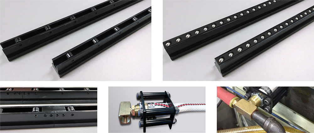
Air Powered Die Lifters/Rollers

Pneumatic (Air Bag) Die Lifters

SISTEMAS NEUMATICOS DE ELEVACION
When to Use Pneumatic Die Lifters:

Use pneumatic die lifters for lighter dies in small to medium presses. Load capacity is approximately 1/2 of a hydraulic rail for inline cylindrical rollers and similar in lift force for the multi-directional ball rollers, but slot size can be much smaller and overall cost much lower. In many applications, performance is astounding. Fitting in slots as small as 1.250” total depth, very large lift capacities are produced with readily available 85 psi shop air. 1,800 lbf/ft/pair for narrow rails and 2,600 lbf/ft/ pair for wide rails. Temperature rating is 150˚ F (65˚ C). Using shop Air eliminates the need for hydraulics and the associated complexities of adding hydraulic systems to the press.

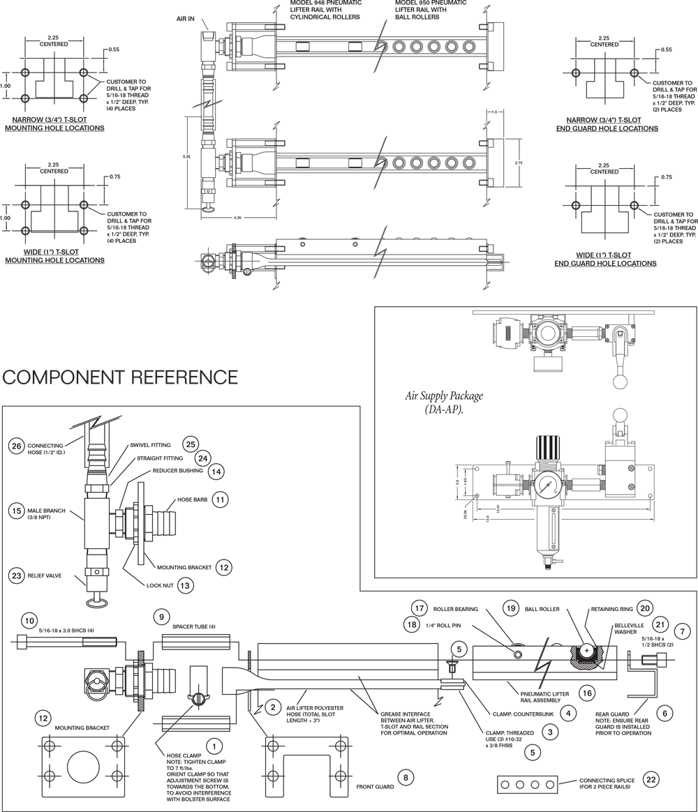
Simple hand operated air valves (or electrically operated valves integrated with other press controls) can be used to actuate the lifters. For an available off the shelf air interface that connects to shop air and provides a Manual Hand Valve, Filter Regulator, and Lockout system, please see information PFA’s Air Package (DA-AP). Designed for standard ¾” and 1” T slots and available to accommodate any press bolster depth, PFA Pneumatic Die Lifters provide a low cost, easy to order, and simple to install option to be used in standalone or integrated applications. Simply add clamps and/or bolster extensions for a complete QDC system.

How They are Used:

Pneumatic Lifting bars with installed rollers are inserted into the T slots and captured between the separate air lift system installed on the front of the press and the guard attached to the back side of the T slot. The air lift bag or hose occupies the space under the rail in the wider slot section providing the lift force when pressurized. If the rail is sized shorter than the slot, a filler bar is added to maintain rail position in the slot. Rails are made to specific dimensions to match the T-slot and achieve the desired lifting height.

Air rail lifting height is specified by the customer to match the insertion height of other components, such as bolster extensions. Activating with 85 psi air, places the lifter “up” ready to receive the die. The die is loaded with the weight transferring from the bolster extensions to the lifters. Once the die is in the press, the lifters are lowered by closing the supply pressure and venting the lines (typically the valve both secures and vents the line).

Systems are provided with rails, guards, the pneumatic fittings, and hose to connect them together along with a relief valve. Customers provide any desired control valves for air and connect to an NPT port or may purchase an “Air Package” consisting of Lockout, Manual Valve, and Filter Regulator for easy integration.
Applications/Sizing

Pneumatic Air Bag Die Lifters Drawing
Standard Rail Configurations
Model No. Slot Rectangular
or T-Slot
Max Load per foot
(lbs./ft./pr.)
Length Max Load Capacity
(lbs./pr.)
Rollers/ Pistons
(per rail)
Cylindrical Rollers 948N 3/4” (.800)
Narrow
T-Slot 1,800 12”
18”
24”
30”
36”
42”
48”
54”
60”
66”
72”
1,800
2,700
3,600
4,500
5,400
6,300
7,200
8,100
9,000
9,900
10,800
4
6
8
10
12
14
16
18
20
22
24
Cylindrical Rollers
948W 1” (.995)
Wide
T-Slot 2,600 12”
18”
24”
30”
36”
42”
48”
54”
60”
66”
72”
2,600
3,900
5,400
6,500
7,800
9,100
10,400
11,700
13,000
14,300
15,600
4
6
8
10
12
14
16
18
20
22
24
Cylindrical Rollers
Ball Rollers 950N 3/4” (.800)
Narrow
T-Slot 1,800 12”
18”
24”
30”
36”
42”
48”
54”
60”
66”
72”
1,800
2,700
3,600
4,500
5,400
6,300
7,200
8,100
9,000
9,900
10,800
11
17
23
29
35
41
47
53
59
65
71
Ball Rollers
950W 1” (.995)
Wide
T-Slot 2,600 12”
18”
24”
30”
36”
42”
48”
54”
60”
66”
72”
2,600
3,900
5,400
6,500
7,800
9,100
10,400
11,700
13,000
14,300
15,600
11
17
23
29
35
41
47
53
59
65
71
Ball Rollers

How to determine available Die Lifter Rail Options

1. List out die sizes and weights.  Calculate die load per foot, per pair of lift rails.  (W=width in feet)

Die 1 Weight ________ ÷ W = ________ lbs./ft./pair
Die 2 Weight ________ ÷ W = ________ lbs./ft./pair
Die 3 Weight ________ ÷ W = ________ lbs./ft./pair

Determine heaviest die per foot. Heaviest die density lb./ft./pair = __________________

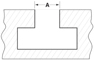
channel-throat-diagram2. Measure T-Slot or Rectangular channel throat.
If A = .800 to 1.000, use Narrow Rails
If A = 1.000 to 1.25, use Wide Rails
If A = <.800 or >1.25, contact PFA

3. For the heaviest die, check the number of available slots under the die:  Number of available slots = _______________

4. Take the die density from Part 1 and find the closest larger lbs./ft./pair from the chart below.  Then move across the top to find your desired die lifter style keeping in mind the Narrow or Wide from Part 2 and the number of available slots from Part 3.  (*Assume 85psi air available)

Die
Density
(lbs./ft./pair)
Narrow Slot
948N
(1,800 lbs./ft./pr.)
Wide Slot
948W
(2,600 lbs./ft./pr.)
1,800 2 Rails 2 Rails
2,600 3 Rails 2 Rails
3,600 4 Rails 3 Rails
3,900 5 Rails 3 Rails
4,500 5 Rails 4 Rails

For larger die weights or fewer available slots mechanical or hydraulic die lifters are recommended.

5. Record the rail model number and number of needed rails from the chart: Model ___________________    Quantity _________

6. For the selected model, confirm that the number of rails always supports the dies as follows:

[W ft.] x [Chart lbs./ft./pair] x [No. of Rails] / 2 = [Lift Capacity] > [Weight lbs.]

Die 1 ______ x ______ x ______ ÷ 2 = ______  >  ______
Die 2 ______ x ______ x ______ ÷ 2 = ______  >  ______

Ensure lift capacity is greater than die weight.

7. With model number and quantity determined, select the rail length desired.   Lifter will be flush with the loading side and should be near the back side but not longer than the bolster slot. Nominal lengths are 12”, 18”, 24”, 30”, 36”, 42”, 48”, 54”, 60”, 66”, 72”, +++    Length = ___________________

If slot is longer than nominal, add filler bar length to end of part number.    Filler = ___________________

8. Finally, the profile and final shape of the rail must be calculated below.

How to Size a “T” Slot:

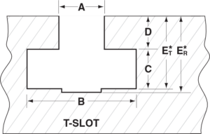
t-slot-diagram1. Measure Neck Height (D), Full Width Depth (ET) and B:
D = ___________
ET = ___________
B = ___________
C = ET – D = ___________

2. Determine Nominal Lift (N)
Typically N = .085” or .125” (1/8” max)
Choose N = ___________________

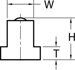
3. Calculate Rail Tab Height (T)
T = C – N – .250” = ___________________ (.xxx)
Rail Tab Height diagram
4. Calculate Rail Height (H)
H = ET – .250 = ___________________ (H.HHH)

For Narrow Rail (.800 < A < 1.00) confirm slot fit
B ≥ 1.300” C ≥ .500” ET ≥ 1.250”

For Wide Rail (1.00 < A < 1.25) confirm slot fit
B ≥ 1.700” C ≥ .575” ET ≥ 1.300”

Pneumatic Die Lifter Part Number
¿LO NECESITA REPARADO DE INMEDIATO? PFA OFRECE SERVICIO REAL™

Aunque la mayoría de los productos de PFA son diseñados a medida, los artículos más críticos se mantienen disponibles para una emergencia. ¿Lo necesitas en 4 horas o menos? ¡Podemos hacerlo! Con el soporte técnico en tiempo real, los productos disponibles y envío el mismo día, a menudo podemos hacer que todo vuelva a la normalidad antes de que hayas tomado el café matutino. Eso es SERVICIO REAL™ (REAL SERVICE™).

¿TIENE UN PROBLEMA DIFÍCIL DE RESOLVER? PFA ES LA SOLUCIÓN.

Trabajamos con nuestros clientes para resolver los problemas existentes y podemos diseñar soluciones personalizadas cuando sea necesario. Con más de 25 años de experiencia en la revisión de aplicaciones y el suministro de productos personalizados, es probable que PFA ya tenga diseñada la solución a tu problema. ¡Llámanos hoy y cuéntanos como podemos ayudarte!

¿SE HA PREGUNTADO CÓMO INCREMENTAR LA PRODUCCIÓN? PFA TE LIBERA DE RETRASOS Y DEMORAS.

Con una solución comprobada de "lean manufacturing" de PFA, tu aplicación siempre funciona. El uso de un sistema de acción lateral KOR-LOK® resultará en un tiempo de diseño y fabricación más corto y reducirá los tiempos de desarrollo. Los clamps de cambio rápido de troquel (QDC) están en stock y listos para enviar, por lo que puede comenzar a ahorrar tiempo y dinero con SMED hoy mismo. Desde piezas de repuesto hasta soluciones complejas, PFA es la respuesta para una producción más rápida y con mayor utilidad.