Hydraulic Adjustable Rocker Clamps

Hydraulic Adjustable Clamp Height Rocker Clamps (Narrow Ledge Like Clamps)

Use Adjustable Rocker Clamps with dies having a cutout clamp position, narrow slot, extended clamp plate and/or variable clamp plate thickness.

Use Adjustable Rocker Clamps with dies having a cutout clamp position, narrow slot, extended clamp plate and/or variable clamp plate thickness.

When to Use Adjustable Rocker Clamps:

Use Adjustable Rocker Clamps with dies having a cutout clamp position, narrow slot in the die or for typical clamp plate applications with variable clamp plate thickness across several dies. Also, ledge brackets, blocks, bars, or ears may be added to dies in some applications to accommodate the clamps and/or small slots cut into the dies to accept the smaller clamp nose.

If systems are setup to have hydraulics removed during stamping, Hydro-Mechanical (L style) clamps (with a mechanical lock) should be selected. If a dedicated hydraulic system is considered, the Fully Hydraulic clamps (with either multiple upper zone control or check valves) may be the preferred choice.

Clamp model and quantity should be selected to provide a total clamping force greater than the total (static and dynamic) force applied to the system during use.

How They Work:

The Adjustable Rocker Clamps are moved into position with the lower body stop set against the die plate (gaps between clamp and die/slot allow movement).

The center height adjustment knob is turned clockwise until the nose of the clamp touches the clamp plate.

When hydraulic pressure is applied, the clamp nose moves downward onto the plate, clamping the die. Hydraulic pressure is maintained during operation, or the Locking Nut (L style) is engaged to allow removal of clamp hydraulic pressure during stamping. To unclamp, hydraulic pressure is removed and clamps open under internal spring force. (Note: Reapplication of hydraulics is required to unlock the Locking Clamps (L) prior to releasing pressure and unclamping). After the clamp is released, the adjustment knob is turned to further open the clamp, as desired.

Standard Configurations

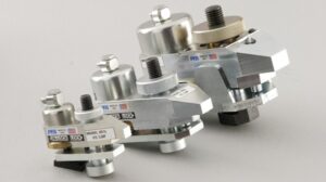
QDC adjustable rocker clamp standard configurations 835 image PFA SMED
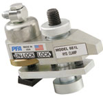
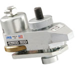
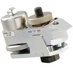
Model 661    /    Model 661L Model 825    /    Model 825L Model 835    /    Model 835L
Clamping Force at 5,000 PSI 3,500 lbs. 8,000 lbs. 17,000 lbs.
Stud Thread Size ⅝” – 11 ¾” – 10 1” – 8
T-Nut/Slot Style ¾” or 1” ¾” or 1” 1”
A 5.25” 7.5” 9.6”
B 1.75” 2.50” 4.00”
C** CLH*
1.0
2.0
3.0
*
Nominal Clamping Range
¾” – 1¼”
1¾” – 2¼”
2¾” – 3¼”
*
Nominal Clamping Range
⅞” – 1¾”
1⅞” – 2¾”
2⅞” – 3¾”
*
Nominal Clamping Range

1¼” – 2½”
2¼” – 3½”
*
D** CLH*
1.0
2.0
3.0

3.75”
4.75”
5.75”

4.75”
5.75”
6.75”

6.00”
7.00”
8.00”
E (Nose Over Plate) .75” .87” 1.00”
F (Width at Plate) 1.10” 2.00” 2.60”
Weight (approx.) 5 lbs. 13 lbs. 32 lbs.
rocker-clamps-chart-image-1 rocker-clamps-chart-image-2 rocker-clamps-chart-image-3

*Nominal clamp height for part number selection. Actual clamp range for selected unit listed in chart. Customs available.

C** and D**= Product clamping range and height dimension is related to nominal Clamping Plate Thickness (CLH) chosen. Allow 1” height clearance for nominal variations and actuation.

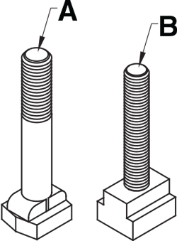
PFA QDC forged T bolt vs. Stud and T nut layout

Clamps are provided with T-Slot Bolt “TSB”  (Item A) or Fully Threaded Stud and T-Nut “STN” (Item B) depending on clamp size, clamping height, and availability.   The new standard will become all Stud and T-Nut arrangements over time.

Identify Your Part Number

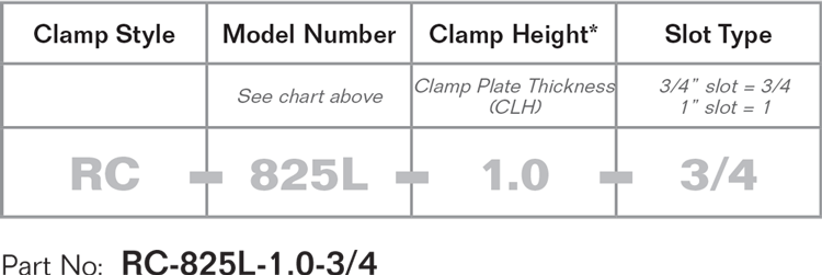
Example:  6,000 lb. die.  Use 8,000 clamps such as Model 825L, clamp plate thickness (CLH) is 1.0” and has 3/4 T-Slot.

QDC Adjustable Rocker Ledge Clamp for SMED part number specification

Please click the button below to be directed to the page that shows System Integrations for PFA products.