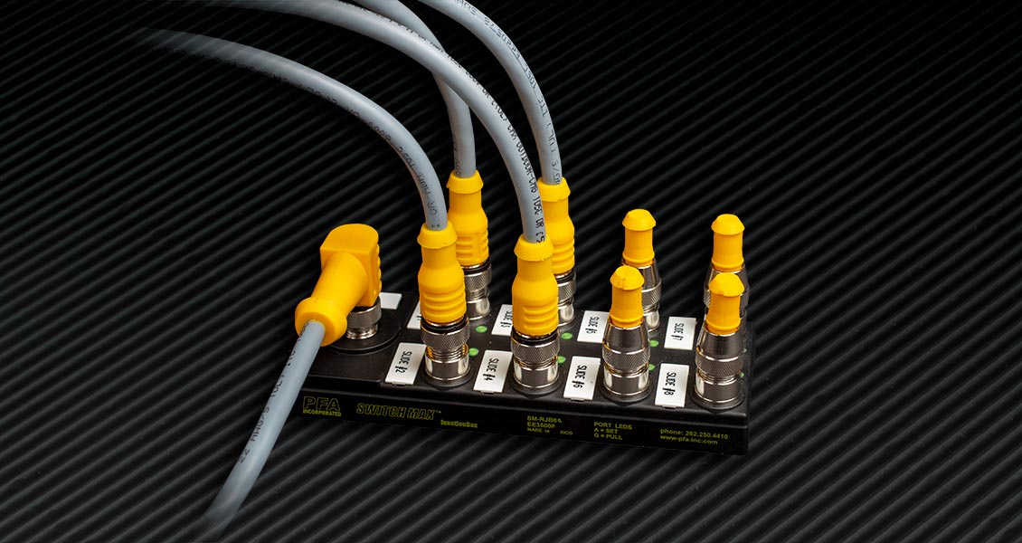
Switchmax® Wiring Examples

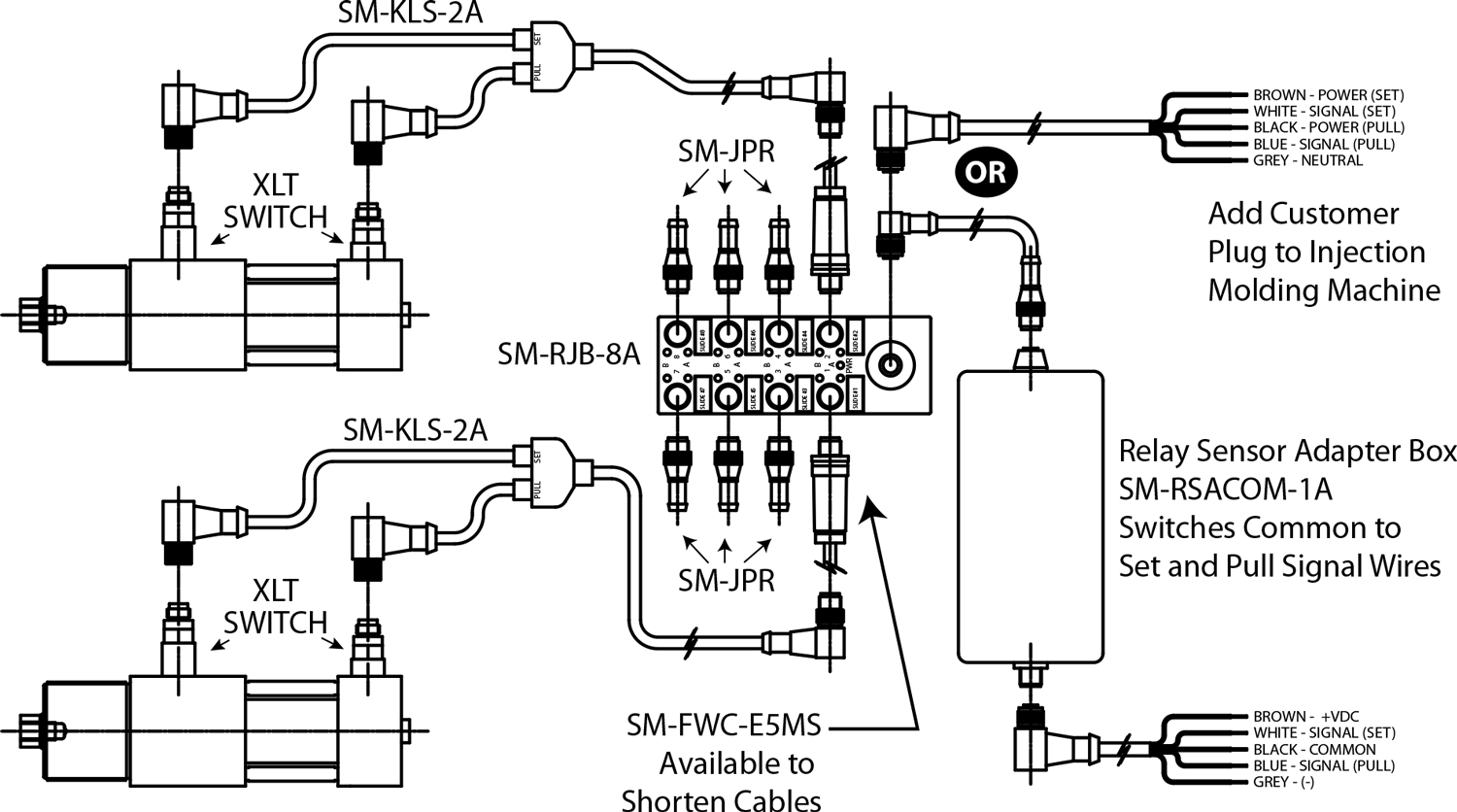
Mechanical Sensor (XLT) KOR-LOK® Side Action Example

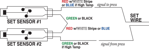
Mechanical Sensor (XLT) KOR-LOK® Side Action Set Example

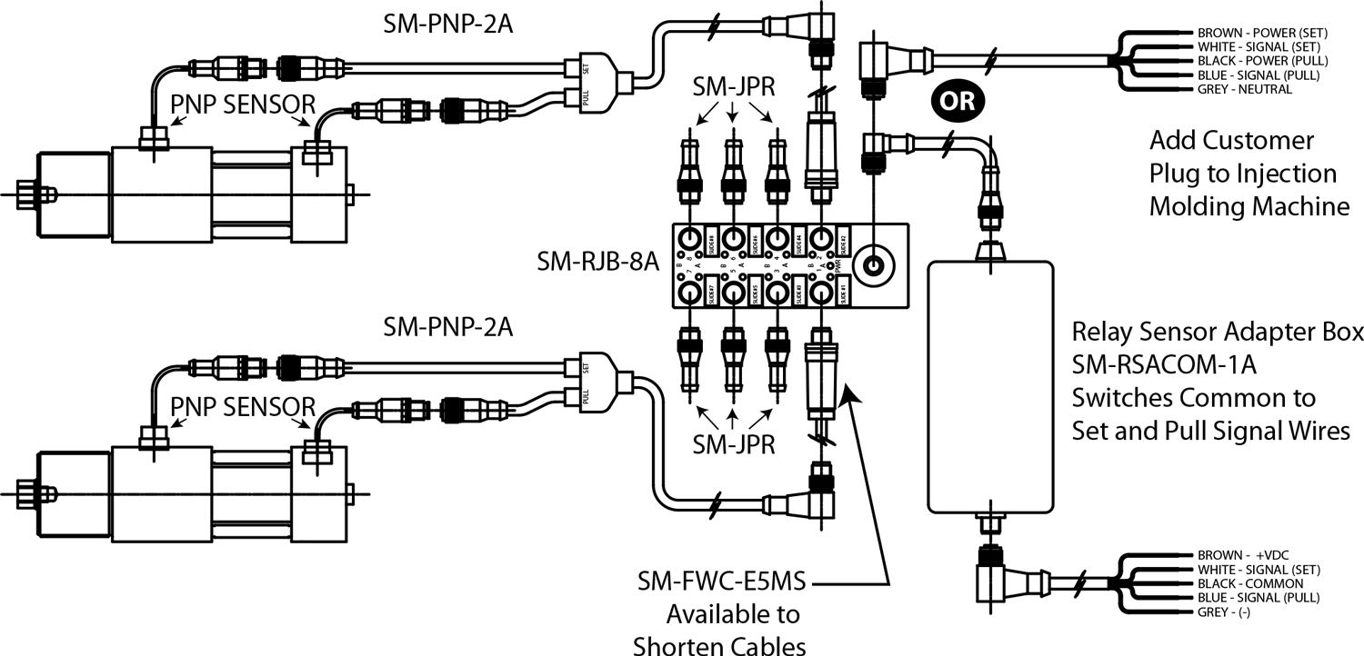
PNP Sensor (3 Wire) Example

PNP Sensor (3 Wire) Example

XLT and XHT PFA Dry Contact/Relay Sensor Details

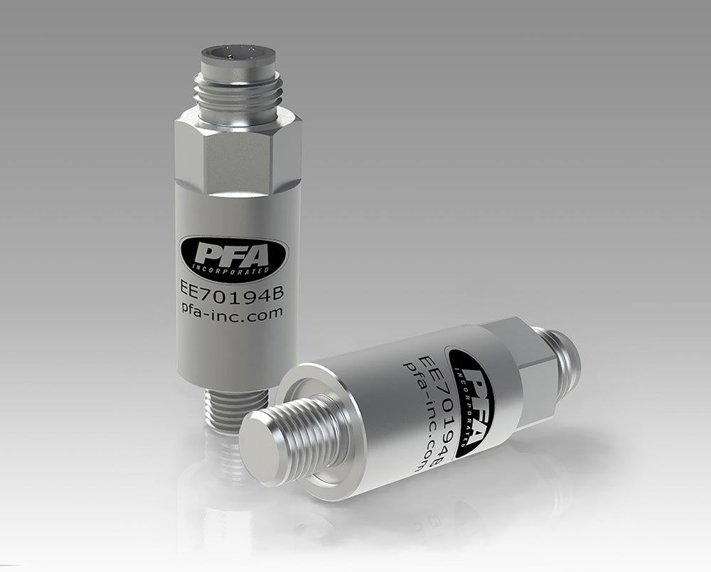
Standard EE 70194/CT70300 (assembly) and High Temperature EE70199/CT705XX (Assemblies)

Hydraulic Locking Cylinder sensor KOR-LOK wiring XLT relay sensor wire colors Common, NC, NO

Fig. 1 – Single Sensor Wiring


Fig. 2 - Multiple Sensor Wiring (Series)

Fig. 2 – Multiple Sensor Wiring (Series)


Figures 1 and 2 show typical manual wire of these sensors in series. When using SWITCHMAX®, the N/C contact is used to cross check operation and provide LED light indications not possible with manual wiring setups.

PFA Relay-style sensors (CT70300 assembly CT70520/21/22… High Temperature Assembly) function as a true dry contact switch. In normal usage, when the target comes “in range” of the sensor, the magnet inside the switch closes a contact to complete the circuit.

CT70300 Assembly Specifications
Part No. on Sensor EE70194 / EE70194B
Cylinder Designation -XLT
Contact Type SPDT (Single-Pole, Double Throw)
Contact Rating 2 Amps @ 12OVAC
1 Amp @ 240VAC
1 Amp @ 24VDC
Temperature -40˚F (-40˚C) to 257˚F (125˚C)
Pressure 3000 psi max.
Install Torque Max. 50 in-lbs. max.
CT70520/21/22…Assembly Specifications
Part No. on Sensor 72-16222-F4 / EE70199
Cylinder Designation -XHT
Contact Type SPDT (Single-Pole, Double Throw)
Contact Rating 4 Amps @ 12OVAC
2 Amp @ 240VAC
3 Amp @ 24VDC
Temperature -40˚F (-40˚C) to 400˚F (204˚C)
Pressure 3000 psi max.
Install Torque Max. 50 in-lbs. max.
XLT Sensor

Relay-style switches offer many benefits to the user. They have no voltage drop when closed nor do they have leakage current when open. In most applications the Normally Open (N/O) connection is used so that when the cores reach set or pull, the relay contacts close to give that indication to the press. In most cases, the Normally Closed (N/C) connection is not used, but is available for use as part of PFA’s SWITCHMAX® Mold Wiring solution.

Connection between the KOR-LOK® Side-Action System and the press, is as simple as connecting two set sensor wires and two pull sensor wires to the two pair of machine control wires. The order of connection for each pair is not important.


Multiple set sensors may be wired in series to provide a single set indication to the press. Similarly, the pull wires may be connected in series. For situations where a core or other part of the mold may be damaged if opened with cores set, it is recommended that a redundant sensor be placed on the core itself and wired in series with the main unit sensors to ensure the core is retracted prior to mold opening.

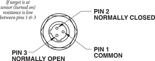
Hydraulic Locking Cylinder sensor KOR-LOK wiring XLT relay sensor pin Common, NC, NO
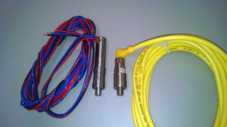
Hydraulic Locking Cylinder XLT and XHT sensors - comparison image

PNP Low Profile PFA Proximity Sensor Details

EE70600/CT70600 Assembly


low-profile-sensor


kor-lok-low-profile-sensor-2

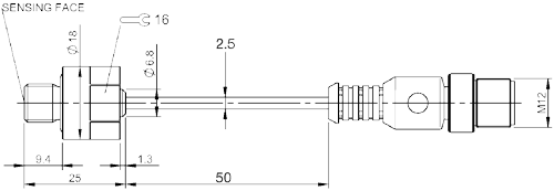
Figures show the PNP sensor and typical cable with flying leads. Manual wiring of these sensors in series is a challenge. When using SWITCHMAX® sensors are easily connected in series, including LED light indication for each sensor.

CT70600 Assembly Specifications
Part No. on Sensor: PFA-EE70600
Cylinder Designation: -PNP
Contact Type: Solid State PNP/NO
Contact Rating: 100 mAmps @ 24VDC
Supply Voltage: 10-30 VDC
Voltage Drop: ≤2.5 VDC
Temperature: -13˚F (-25˚C) to 175˚F (80˚C)
Install Torque Max.: 50 in-lbs. max.

Low Profile PNP sensors offer benefits to the user when fitting The KOR-LOK unit into demandingly small applications or when Integrating with other actuators using similar PNP sensor logic. PFA’s PNP option has a low voltage drop, typically allowing multiple sensors to be connected together to facilitate a single input to the machine control. Sensor integration is easily accomplished with PFA’s SWITCHMAX® connectivity solution with PNP designated splitter cables.


In a generic application the Normally Open Sensor is paired with an individual cable to provide power and route the signal. To use the sensors individually, Power +24VDC (Brown wire) and Neutral 0 VDC (Blue wire) is required, as well as some method of integrating the sensor signal (Black wire) to the press. Various schemes are used to accomplish this task for molds with multiple cylinders, however, PFA recommends SWITCHMAX® to provide a plug and play serial connection of sensors into single inputs for set and pull, while also providing operator side indication and troubleshooting capability.

While proper indication is expected, PFA cautions that for situations where a core or other part of the mold may be damaged if opened with cores set, it is recommended that a redundant sensor be placed on the core itself and wired in series with the main unit sensors to ensure the core is retracted prior to mold opening.

Hydraulic Locking Cylinder PNP sensor KOR-LOK wiring schematic
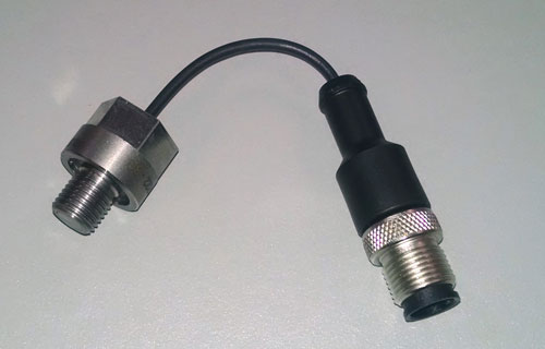
Hydraulic Locking Cylinder PNP sensor with M12 connector
KL112 PNP Low Profile Sensor